````

Why is a color code used for resistors?

There are many different types of Resistors available which can be used in both electrical and electronic circuits to control the flow of current or to produce a voltage drop in many different ways. But to do this, the actual resistor needs to have some form of “resistive” or “resistance” value. Resistors are available in a range of different resistance values from fractions of an Ohm ( Î© ) to millions of Ohms.
Obviously, it would be impractical to have available resistors of every possible value, for example, 1Ω2Ω3Ω4Ω, etc, because literally tens of hundreds of thousands, if not tens of millions of different resistors would need to exist to cover all the possible values. Instead, resistors are manufactured in what are called “preferred values” with their resistance value printed onto their body in colored ink.


The resistance value, tolerance, and wattage rating are generally printed onto the body of the resistor as numbers or letters when the body of the resistor is big enough to read the print, such as large power resistors. But when the resistor is small such as a 1/4 watt carbon or film type, these specifications must be shown in some other manner as the print would be too small to read.
So to overcome this, small resistors use colored painted bands to indicate both their resistive value and their tolerance with the physical size of the resistor indicating its wattage rating. These colored painted bands produce a system of identification generally known as a Resistors Colour Code.
An international and universally accepted resistor color code scheme was developed many years ago as a simple and quick way of identifying a resistor ohmic value no matter what its size or condition. It consists of a set of individual colored rings or bands in spectral order representing each digit of the value of the resistor.
The resistor color code markings are always read one band at a time starting from the left to the right, with the larger width tolerance band oriented to the right side indicating its tolerance. By matching the color of the first band with its associated number in the digit column of the color chart below the first digit is identified and this represents the first digit of the resistance value.
Again, by matching the color of the second band with its associated number in the digit column of the color chart we get the second digit of the resistance value and so on. Then the resistor color code is read from left to right as illustrated below:
x

Why Birds don't get electric shock while sitting on transmission lines?

Current flows in a loop (which means the circuit is closed). A bird sitting on a transmission line does not complete the circuit. If the same bird keeps one leg on one track and another leg (or any part of its body) on another line(or the neutral points), then it will get roasted.
Consider this circuit where a bird sits on the wire:
The values R1 and R2 are resistances of the line. Electricity takes the path of least resistance. The two legs of the bird which are perched on the same line do not complete the circuit. The R_Bird( resistance of the bird’s body) is much higher than that of the line, so the bird might not experience high current. The potential difference between the two legs of the bird is the same( since the resistance of the line is the same throughout). The current flows on. The bird is safe.
Now consider this scenario:
A bird sitting on a line decides to fly away and raises the wings. With one wing touching the neighboring line and the leg on the first line, this creates a closed circuit. Thus electricity (following the path of least resistance) will detect a potential difference between the wing (which touches the other line) and the leg(which is placed on the first line). The current tries to take on that path creating a short-circuit. Eventually, the bird gets zapped and falls off the line. Now the current will continue to flow on.

GATE 2019: Mock Test for all the subjects now available on gate.iitm.ac.in, check updates here

GATE 2019 Mock Tests; Image Credit: gate.iitm.ac.in
GATE 2019 Mock Tests; Image Credit: gate.iitm.ac.in 
Graduate Aptitude Test in Engineering, GATE 2019 mock tests are now available on the official website gate.iitm.ac.in. Candidates who have applied for the examination can check out the mock tests on the official website. The correction window for personal details has closed. The window to apply for the change in GATE 2019 exam city is expected to be activated within this week. A direct link to mock tests is provided below.

What is power electronics?


Power electronic devices are those devices which can control a large amount of power with the help of smart electronics
·         power electronics deals with electronics for control and conversion of large amount  of electrical power
·         the major component of power electronics circuit is the thirstier which operating as a fast switching semiconductor and it function is to modulate the power in AC and DC system

Microcontrollers - 8051 Interrupts

Microcontrollers - 8051 Interrupts
Interrupts are the events that temporarily suspend the main program, pass the control to the external sources and execute their task. It then passes the control to the main program where it had left off.
8051 has 5 interrupt signals, i.e. INT0, TFO, INTR1, TF1, RI/TI. Each interrupt can be enabled or disabled by setting bits of the IE register and the whole interrupt system can be disabled by clearing the EA bit of the same register.

IE (Interrupt Enable) Register

This register is responsible for enabling and disabling the interrupt. EA register is set to one for enabling interrupts and set to 0 for disabling the interrupts. Its bit sequence and their meanings are shown in the following figure.
IE Register

Microcontrollers 8051 Input Output Ports

8051 microcontrollers have 4 I/O ports each of 8-bit, which can be configured as input or output. Hence, total 32 input/output pins allow the microcontroller to be connected with the peripheral devices.
  • Pin configuration, i.e. the pin can be configured as 1 for input and 0 for output as per the logic state.
    • Input/Output (I/O) pin − All the circuits within the microcontroller must be connected to one of its pins except P0 port because it does not have pull-up resistors built-in.
    • Input pin − Logic 1 is applied to a bit of the P register. The output FE transistor is turned off and the other pin remains connected to the power supply voltage over a pull-up resistor of high resistance.
  • Port 0 − The P0 (zero) port is characterized by two functions −
    • When the external memory is used then the lower address byte (addresses A0A7) is applied on it, else all bits of this port are configured as input/output.
    • When P0 port is configured as an output then other ports consisting of pins with built-in pull-up resistor connected by its end to 5V power supply, the pins of this port have this resistor left out.

Input Configuration

If any pin of this port is configured as an input, then it acts as if it “floats”, i.e. the input has unlimited input resistance and in-determined potential.

Output Configuration

When the pin is configured as an output, then it acts as an “open drain”. By applying logic 0 to a port bit, the appropriate pin will be connected to ground (0V), and applying logic 1, the external output will keep on “floating”.
In order to apply logic 1 (5V) on this output pin, it is necessary to build an external pullup resistor.

Port 1

P1 is a true I/O port as it doesn’t have any alternative functions as in P0, but this port can be configured as general I/O only. It has a built-in pull-up resistor and is completely compatible with TTL circuits.

Port 2

P2 is similar to P0 when the external memory is used. Pins of this port occupy addresses intended for the external memory chip. This port can be used for higher address byte with addresses A8-A15. When no memory is added then this port can be used as a general input/output port similar to Port 1.

Port 3

In this port, functions are similar to other ports except that the logic 1 must be applied to appropriate bit of the P3 register.

Pins Current Limitations

  • When pins are configured as an output (i.e. logic 0), then the single port pins can receive a current of 10mA.
  • When these pins are configured as inputs (i.e. logic 1), then built-in pull-up resistors provide very weak current, but can activate up to 4 TTL inputs of LS series.
  • If all 8 bits of a port are active, then the total current must be limited to 15mA (port P0: 26mA).
  • If all ports (32 bits) are active, then the total maximum current must be limited to 71mA.

Microcontrollers - 8051 Pin Description

The pin diagram of 8051 microcontroller looks as follows −
  • Pins 1 to 8 − These pins are known as Port 1. This port doesn’t serve any other functions. It is internally pulled up, bi-directional I/O port.
  • Pin 9 − It is a RESET pin, which is used to reset the microcontroller to its initial values.
  • Pins 10 to 17 − These pins are known as Port 3. This port serves some functions like interrupts, timer input, control signals, serial communication signals RxD and TxD, etc.
  • Pins 18 & 19 − These pins are used for interfacing an external crystal to get the system clock.
  • Pin 20 − This pin provides the power supply to the circuit.
  • Pins 21 to 28 − These pins are known as Port 2. It serves as I/O port. Higher order address bus signals are also multiplexed using this port.
  • Pin 29 − This is PSEN pin which stands for Program Store Enable. It is used to read a signal from the external program memory.
  • Pin 30 − This is EA pin which stands for External Access input. It is used to enable/disable the external memory interfacing.
  • Pin 31 − This is ALE pin which stands for Address Latch Enable. It is used to demultiplex the address-data signal of port.
  • Pins 32 to 39 − These pins are known as Port 0. It serves as I/O port. Lower order address and data bus signals are multiplexed using this port.
  • Pin 40 − This pin is used to provide power supply to the circuit.

Microcontrollers - 8051 Architecture

8051 microcontroller is designed by Intel in 1981. It is an 8-bit microcontroller. It is built with 40 pins DIP (dual inline package), 4kb of ROM storage and 128 bytes of RAM storage, 2 16-bit timers. It consists of are four parallel 8-bit ports, which are programmable as well as addressable as per the requirement. An on-chip crystal oscillator is integrated in the microcontroller having crystal frequency of 12 MHz.

    Let us now discuss the architecture of 8051 Microcontroller.

In the following diagram, the system bus connects all the support devices to the CPU. The system bus consists of an 8-bit data bus, a 16-bit address bus and bus control signals. All other devices like program memory, ports, data memory, serial interface, interrupt control, timers, and the CPU are all interfaced together through the system bus.
8051 Architecture

8085 PIN DESCRIPTION

Properties:

  • It is a 8-bit microprocessor
  •  Manufactured with N-MOS technology
  •  40 pin IC package
  •  It has 16-bit address bus and thus has 216 = 64 KB addressing capability.
  •  Operate with 3 MHz single-phase clock
  •  +5 V single power supply
The logic pin layout and signal groups of the 8085nmicroprocessor are shown in Fig. 6. All the signals are classified into six groups:
  • Address bus
  •  Data bus
  •  Control & status signals
  •  Power supply and frequency signals
  •  Externally initiated signals
  •  Serial I/O signals
                                                    Fig.1- 8085 microprocessor pin layout

Intel 8085 Microprocessor architecture

Intel 8085 is a 8-bit microprocessor. It was the most successful 8-bit microprocessor. Here is an overview of this.
In 8085 there are mainly three components:
1) Arithmetic and Logical Unit(ALU)
2) Control Unit(CU)
3) Registers

1. ALU performs the arithmetic and logical operations like Add, Sub, Increment, Decrement, OR, AND, Complement etc. ALU uses the accumulator to hold the first operand and after operation accumulator holds the result. Second operand is stored within the temporary register.
Another registrer called Flag register is associated with the ALU. Flag registershows the status of result after arithmetic or logical operation.
Flag is a 8-bit register out of that 5 shows the status and the remainig five bits are undefined. The five flags are as follows:
1. Carry flag: if after the arithmetic operation a carry is generated, Carry flag becomes 1 otherwaise the value is zero.
2. Parity flag: Parity bit is used for error detection in data. 8085 uses even parity method for error detection. If the number of ones in result are even parity flag becomes, othewase one.
3. Auxillary carry flag: if a carry is generated fron lower nibble(A3-A0) towards the higher nibble(A7-A4) than Auxirry carry becomes one otherwase the value is zero.this flag is used in case of BCD operations.
4. Zero flag: This flag tells that wether contents of register are zero or non zero? If zero flag is set(1) that means register contents are zero.
5. Sign flag: the value of this flag is equal to the MSB of accumulator. In case signed arithmetic it shows the sign of result i.e. possitve or negative. If sign flag is set than result is negative otherwase the result is possitive.


Block Diagram of Intel 8085 Microprocessor

Difference between Analog and Digital circuit


Analog Circuits

  1. These circuits operate on continuous-valued signals(commonly referred to as analog signals).                    
  2. Analog circuits are difficult to design since each component has to be placed by hand as automation techniques for designing these circuits fail to do the job efficiently.
  3. No conversion of input signals are required before processing i.e. input signal is analog, the circuit directly performs various logical operations and produces an analog output.
  4. The man power available to design analog circuits is very low, this results in long time to market the finished products.
  5. Analog circuits are mostly custom made and lack flexibility. 

Digital Circuits

  1. These circuits operate on signals that exist only at two levels i.e. 0's and 1's (binary number system).
  2. On the other hand digital circuits are easy to design since automation technique can be applied at various levels of circuit design. This involves minimum human interaction.
  3. In digital circuits, the input signals are converted from analog to digital form before it is processed, i.e. the digital circuit is capable of processing digital signals only, and produces output which is again converted back from digital to analog signals so that the output gives meaning full results that can be understood by humans.
  4. The available manpower to design digital circuits is significantly large compared to that of analog circuit designers.
  5. Digital circuits have a high degree of flexibility.

Arduino - Conditional Operator ? :

The conditional operator ? : is the only ternary operator in C.

? : conditional operator Syntax

expression1 ? expression2 : expression3
Expression1 is evaluated first. If its value is true, then expression2 is evaluated and expression3 is ignored. If expression1 is evaluated as false, then expression3 evaluates and expression2 is ignored. The result will be a value of either expression2 or expression3 depending upon which of them evaluates as True.
Conditional operator associates from right to left.
Example
/* Find max(a, b): */
max = ( a > b ) ? a : b;
/* Convert small letter to capital: */
/* (no parentheses are actually necessary) */
c = ( c >= 'a' && c <= 'z' ) ? ( c - 32 ) : c;

Arduino - switch case statement

Similar to the if statements, switch...case controls the flow of programs by allowing the programmers to specify different codes that should be executed in various conditions. In particular, a switch statement compares the value of a variable to the values specified in the case statements. When a case statement is found whose value matches that of the variable, the code in that case statement is run.
The break keyword makes the switch statement exit, and is typically used at the end of each case. Without a break statement, the switch statement will continue executing the following expressions ("falling-through") until a break, or the end of the switch statement is reached.

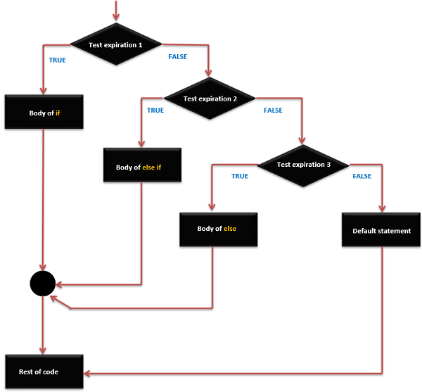
Arduino - If…else if …else statement

The if statement can be followed by an optional else if...else statement, which is very useful to test various conditions using single if...else if statement.
When using if...else if…else statements, keep in mind −
  • An if can have zero or one else statement and it must come after any else if's.
  • An if can have zero to many else if statements and they must come before the else.
  • Once an else if succeeds, none of the remaining else if or else statements will be tested.

if … else if …else Statements Syntax

if (expression_1) {
   Block of statements;
}

else if(expression_2) {
   Block of statements;
}
.
.
.

else {
   Block of statements;
}

if … else if … else Statement Execution Sequence

If Else If Else Statement

Example

/* Global variable definition */
int A = 5 ;
int B = 9 ;
int c = 15;

Void setup () {

}

Void loop () 
{
   /* check the boolean condition */
   if (A > B)
 /* if condition is true then execute the following statement*/
 {
      A++;
   }
   /* check the boolean condition */
   else if ((A == B )||( B < c) ) 
/* if condition is true then 
      execute the following statement*/ 
 {
      C = B* A;
   }else
      c++;
}

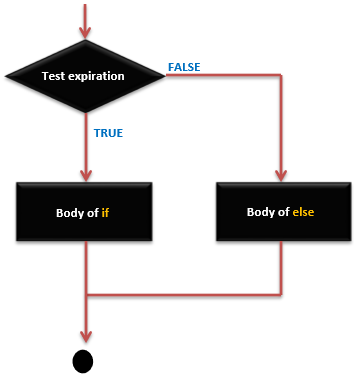
Arduino - If …else statement

An if statement can be followed by an optional else statement, which executes when the expression is false.

if … else Statement Syntax

if (expression) {
   Block of statements;
}
else {
   Block of statements;
}

if…else Statement – Execution Sequence

If Else Statement

Example

/* Global variable definition */
int A = 5 ;
int B = 9 ;

Void setup () {

}

Void loop () {
   /* check the boolean condition */
   if (A > B) 
 /* if condition is true then execute the following statement*/  
{
      A++;
   }else {
      B -= A;
   }
}

Arduino - Control Statements

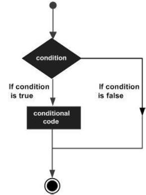
Decision making structures require that the programmer specify one or more conditions to be evaluated or tested by the program. It should be along with a statement or statements to be executed if the condition is determined to be true, and optionally, other statements to be executed if the condition is determined to be false.
Following is the general form of a typical decision making structure found in most of the programming languages −
Decision Making

Arduino - Operators

An operator is a symbol that tells the compiler to perform specific mathematical or logical functions. C language is rich in built-in operators and provides the following types of operators −
  • Arithmetic Operators
  • Comparison Operators
  • Boolean Operators
  • Bitwise Operators
  • Compound Operators

Arithmetic Operators

Assume variable A holds 10 and variable B holds 20 then −
Operator name Operator simple Description Example
assignment operator = Stores the value to the right of the equal sign in the variable to the left of the equal sign. A = B
addition + Adds two operands A + B will give 30
subtraction - Subtracts second operand from the first A - B will give -10
multiplication * Multiply both operands A * B will give 200
division / Divide numerator by denominator B / A will give 2
modulo % Modulus Operator and remainder of after an integer division B % A will give 0

Arduino - Arithmetic Operators

Assume variable A holds 10 and variable B holds 20 then −
Operator name Operator simple Description Example
assignment operator = Stores the value to the right of the equal sign in the variable to the left of the equal sign. A = B
addition + Adds two operands A + B will give 30
subtraction - Subtracts second operand from the first A - B will give -10
multiplication * Multiply both operands A * B will give 200
division / Divide numerator by denominator B / A will give 2
modulo % Modulus Operator and remainder of after an integer division B % A will give 0

Arduino - Variables & Constants

Before we start explaining the variable types, a very important subject we need to make sure, you fully understand is called the variable scope.

What is Variable Scope?

Variables in C programming language, which Arduino uses, have a property called scope. A scope is a region of the program and there are three places where variables can be declared. They are −
  • Inside a function or a block, which is called local variables.
  • In the definition of function parameters, which is called formal parameters.
  • Outside of all functions, which is called global variables.

Arduino - Data Types

Data types in C refers to an extensive system used for declaring variables or functions of different types. The type of a variable determines how much space it occupies in the storage and how the bit pattern stored is interpreted.
The following points  provides all the data types that you will use during Arduino programming.
void     Boolean           char     Unsigned char     byte       int      Unsigned int    word        
 long      Unsigned long  short float              double array     String-char array     String-object

 
Powered by Blogger