````

Arduino - Operators

An operator is a symbol that tells the compiler to perform specific mathematical or logical functions. C language is rich in built-in operators and provides the following types of operators −
  • Arithmetic Operators
  • Comparison Operators
  • Boolean Operators
  • Bitwise Operators
  • Compound Operators

Arithmetic Operators

Assume variable A holds 10 and variable B holds 20 then −
Operator name Operator simple Description Example
assignment operator = Stores the value to the right of the equal sign in the variable to the left of the equal sign. A = B
addition + Adds two operands A + B will give 30
subtraction - Subtracts second operand from the first A - B will give -10
multiplication * Multiply both operands A * B will give 200
division / Divide numerator by denominator B / A will give 2
modulo % Modulus Operator and remainder of after an integer division B % A will give 0

Arduino - Arithmetic Operators

Assume variable A holds 10 and variable B holds 20 then −
Operator name Operator simple Description Example
assignment operator = Stores the value to the right of the equal sign in the variable to the left of the equal sign. A = B
addition + Adds two operands A + B will give 30
subtraction - Subtracts second operand from the first A - B will give -10
multiplication * Multiply both operands A * B will give 200
division / Divide numerator by denominator B / A will give 2
modulo % Modulus Operator and remainder of after an integer division B % A will give 0

Arduino - Variables & Constants

Before we start explaining the variable types, a very important subject we need to make sure, you fully understand is called the variable scope.

What is Variable Scope?

Variables in C programming language, which Arduino uses, have a property called scope. A scope is a region of the program and there are three places where variables can be declared. They are −
  • Inside a function or a block, which is called local variables.
  • In the definition of function parameters, which is called formal parameters.
  • Outside of all functions, which is called global variables.

Arduino - Data Types

Data types in C refers to an extensive system used for declaring variables or functions of different types. The type of a variable determines how much space it occupies in the storage and how the bit pattern stored is interpreted.
The following points  provides all the data types that you will use during Arduino programming.
void     Boolean           char     Unsigned char     byte       int      Unsigned int    word        
 long      Unsigned long  short float              double array     String-char array     String-object

Arduino - Program Structure

In this chapter, we will study in depth, the Arduino program structure and we will learn more new terminologies used in the Arduino world. The Arduino software is open-source. The source code for the Java environment is released under the GPL and the C/C++ microcontroller libraries are under the LGPL.
Sketch − The first new terminology is the Arduino program called “sketch”.

Structure

Arduino programs can be divided in three main parts: Structure, Values (variables and constants), and Functions. In this tutorial, we will learn about the Arduino software program, step by step, and how we can write the program without any syntax or compilation error.

Arduino - Installation

After learning about the main parts of the Arduino UNO board, we are ready to learn how to set up the Arduino IDE. Once we learn this, we will be ready to upload our program on the Arduino board.
In this section, we will learn in easy steps, how to set up the Arduino IDE on our computer and prepare the board to receive the program via USB cable.
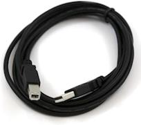
Step 1 − First you must have your Arduino board (you can choose your favorite board) and a USB cable. In case you use Arduino UNO, Arduino Duemilanove, Nano, Arduino Mega 2560, or Diecimila, you will need a standard USB cable (A plug to B plug), the kind you would connect to a USB printer as shown in the following image.
USB Cable

Introduction with ardunio

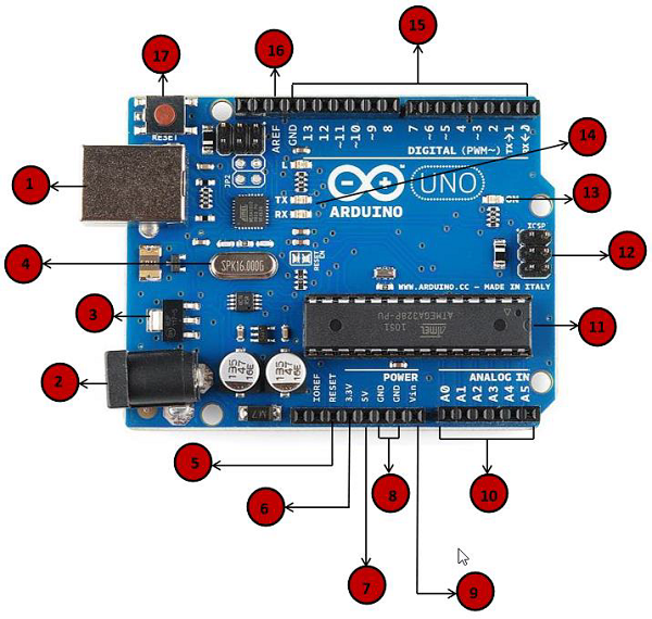
In this chapter, we will learn about the different components on the Arduino board. We will study the Arduino UNO board because it is the most popular board in the Arduino board family. In addition, it is the best board to get started with electronics and coding. Some boards look a bit different from the one given below, but most Arduinos have majority of these components in common.
Board Description

CD-DVD / FDD Stepper Motor labeling

How to Use the Stepper Motors of CD/DVD/FDD Drives

Generally stepper motor's are costly as compared to a normal DC motor. Stepper Motor is probably the first thing you need to know about, if you are interested to learn robotics.(the next one would be Servo Motors). In India the stepper motor may cost from 250 to 500 rupees,(6$-10$) so to reduce the cost you can use a stepper motor from waste floppy drives or CD-DVD drives.
The stepper motor used for running the disk in the fdd are generally hybrid stepper motor. In case you want to know what is stepper motor can you can read in Wikipedia , it has detailed description about Hybrid Stepper Motor.

Infrared Sensors or IR Sensors

Introduction
Infrared technology addresses a wide variety of wireless applications. The main areas are sensing and remote controls. In the electromagnetic spectrum, the infrared portion is divided into three regions: near-infrared region, mid-infrared region and far-infrared region.
The wavelengths of these regions and their applications are shown below.
·         Near-infrared region — 700 nm to 1400 nm — IR sensors, fiber optic
·         Mid-infrared region — 1400 nm to 3000 nm — Heat sensing
·         Far infrared region — 3000 nm to 1 mm — Thermal imaging
The frequency range of infrared is higher than microwave and lesser than visible light.
For optical sensing and optical communication, photo optics technologies are used in the near-infrared region as the light is less complex than RF when implemented as a source of the signal. Optical wireless communication is done with IR data transmission for short-range applications.

How to Connect Arduino Uno to Android via Bluetooth

Arduino is one of the most popular microcontroller-based electronics prototyping platforms available in the market. The area of applications of Arduino is huge ranging from simple LED driving circuits to complex internet-based weather monitoring circuits.
One of the in-demand concepts is communication between the Arduino board and Android-based smartphone or tablet. Even though Arduino can be configured to perform many complicated operations, it would be more beneficial if those operations are controlled using an Android phone.
In order to allow communication between Arduino and Android-based smartphone, we need to use Bluetooth communication. Almost all Android-based devices have built-in Bluetooth communication module. Hence, we need to use an external Bluetooth Module for Arduino board.

Arduino Android Communication Bluetooth

555 Timer PWM Audio Amplifier

The ubiquitous 555 timer IC handles audio signals in its own pulse-width modulation (PWM) way. Here, the 555 IC works in astable mode. The switching frequency can be varied from 65 kHz to 188 kHz. Selection of PWM frequency depends on the amplitude of the input signal as well as the load impedance. By adjusting VR1, you can ensure comfortable listening with low audio distortion.
In pulse-width modulation, the carrier frequency’s pulse width varies as a function of the amplitude of the input audio signal. Feedback capacitor C2 ensures faithful reproduction of the audio signal. An output L-C filter is the common approach for a reasonable rejection of the carrier frequencies. For simplicity, it is omitted here. Moreover, the speakers cannot respond to the high-frequency signal. They respond to the average DC level modulated with the audio signal that we feed in from the input. Of course, the audio quality is not as good as that of a professional system, but it would be definitely an amazing experience to listen audio through a 555 chip with room-filling volume.

IC 555 Timer Tester

This simple and easy-to-use gadget not only tests the IC 555 timer in all its basic configurations but also tests the functionality of each pin of the timer. Once a timer is declared fit by this gadget, it will function satisfactorily in whatever mode or configuration you may try it.
The two basic configurations in which a timer IC 555 can be used are the astable and the monostable modes of operation.
When the DPDT switch (S2) is in position 1-1, the timer under test automatically gets wired as a monostable multivibrator. In this case, the monoshot can be triggered by the microswitch (S1). The debouncing circuit constituted by the two NAND gates of IC1 (N1 and N2) produces a clean rectangular pulse when the microswitch is pressed. Resistor R3, capacitor C1 and diode D1 ensure that the trigger terminal of timer IC 555 (pin 2 is the trigger terminal) gets the desired positive-to-ground trigger pulse. This differentiator circuit also ensures that the width of the trigger pulse is less than the expected monoshot output pulse.

7F4_AFA_1


The monoshot output pulse width is a function of the series combination of resistor R8 and potentiometer

World’s smallest transistor is just 1 nanometer wide

For more than a decade, engineers have been eyeing the finish line in the race to shrink the size of components in integrated circuits. They knew that the laws of physics had set a 5-nanometer threshold on the size of transistor gates among conventional semiconductors, about one-quarter the size of high-end 20-nanometer-gate transistors now on the market.
Some laws are made to be broken, or at least challenged.
Schematic of a transistor with a molybdenum disulfide channel and 1 nanometer carbon nanotube gate. (Credit: Sujay Desai/UC Berkeley)

 
Powered by Blogger